Thermal Imaging Study

What is Thermal Imaging?
This is the practice of monitoring electrical equipment with typically infra-red (IR) cameras. This monitoring and picturing heat elements of equipment. It's as simple as that.
Types & How it's Achieved?
There are various and many ways of achieving such imaging, however here at ElecSpec we have narrowed this down into three categories, labeling the solutions not in application but in a way that we believe will be more relevant to clients, understanding the implementation.
Each solution as always obtaining its own merit however in our opinion there's only one clear solution.
1) Non-Intrusive, Full System Analysis, Thermal Imaging Camera Study
2) Semi- Intrusive, Partial System Analysis Thermal Imaging Camera Study
3) Non-Intrusive Permanent Selective Thermal Imaging Camera Study
There is a fourth solution that I have sadly bared witness, this is removing all covers and doors, using the camera to complete the study, but without mentioning the obviously HUGE danger of this solution, it also lets heat escape by removing compartment doors and not only would it give poor results because of this but let me stress this again it's SO DANGEROUS! Safe to say we don't endorse.
The Electricity at Work Regulations of 1989 places a “duty of care” on employers and landlords to maintain electrical systems to prevent danger.
Such maintenance is typically advised and undertaken by manufacturers, however in our modern day society in many cases traditional inspection and testing is not possible with the 24/7 requirements where it is not possible to isolate. Such practices are common in industries such as hospitals, data centers, factories, universities etc. However, the regulations apply to all industries regardless of application and it is imperative to carry out as much inspection and test work as possible. Thermal imaging offers and effective solution for determining the presence of potential problems, this without the need to isolate circuits. Images can be taken, in most cases all connections and this is an
Why do you need Thermal Imaging?
Ever since I began my career in the electrical industry, there is one paraphrase that has stuck out above the rest, "loose wires cause", yes you know it also, fires! Thermal imaging is a method of identifying hot spots on a system, monitoring systems to ensure they are functioning from an electrical connection point of view, as the day it was purchased, reducing those fires... Simply loose connections cause extra heat (resistance & Ohms law again), this heat is picked up on the camera and we know we have a potential fault, perfect maintenance solution.
essential accompaniment alongside usual visual inspections and live testing ensuring your client/landlord are meeting obligations under legislation.
Solution Number One,
This solution is becoming increasing common in the industry, this method is typical of searching for heat in such, sadly
terrible incidences as natural disasters, such as earthquakes, searching rubble for heat sources, a saving life piece of equipment. The the same principle is used in L.V, however, in this case, the camera is used to scan a piece of equipment to derive a complete heat signature of that complete solution. The results are incredible and really give an excellent and exact heat signature of the equipment, typically a report is about 300 pages long in my experience, plenty to read.
It completely ignores the enclosure and builds a really good photograph of heat, perfect solution for all applications, obviously, the camera is more expensive but it's a one-off cost, it's non-intrusive and in our professional opinion, it's a no brainer.

Solution Number Two,
This solution is quite a common one in the industry, or at least it has been, it involves the same as above but instead of
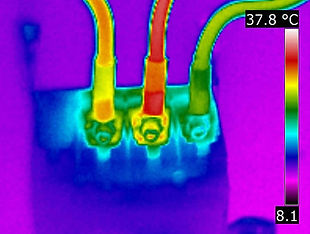
viewing the equipment from in front of the switchboard, completely independent, the user has specific locations of which a viewing window is placed. This window is special glass that allows IR to be passed through with no distortion and works exactly like the picture on the right, which is the reason I have called this semi-intrusive but I feel it's a hard judgment by ourselves.
The main drawbacks of this solution are obviously you can't have these windows everywhere, they are actually difficult for manufacturers to fit within their designs and of course, you can therefore only monitor certain connections and this is a huge limitation or this solution.
From a practical point of view, they are also very difficult to realise what

you are looking at because you have a very narrow view of the picture and it can be hard to tell which area is which, this is without mentioning pointing the gun in the right place.
Overall we are not big fans, especially when the first solution is 100 times better, cheaper short term, dependant on if you buy your own camera, but either way solution number ones results are serious out of the league of this solution
Solution Number Three,
The final solution is a permanent monitoring solution, as shown in the image below, the cameras are placed directly aimed

at the required connection to be monitored and these are connected to a monitoring unit that reports the temperatures 24/7. This delivers accurate data available at any time where historical trends/graphs can be plotted and
compared to accurately indicate the need for maintenance, however, one large aspect that needs to always be accounted is the load. Because this will fluctuate, so will the temperature and it is always worth comparing data around the same time of the week, to give an accurate analysis of the equipment. The main drawback of this solution is the cost and its implementation. This being A. very costly and B. difficult to
implement on smaller breakers, so we here would advise that if this is something that is really required, only fit these to main components, typically the largest and most important aspects such as main incoming ACB's. On smaller equipment such as MCCB's it's very difficult to phyiscally fit them and also gets extremely costly.